1:32 SCALE ARDUINIO BLUETOOTH CONTROLLED CARS

>> 00: PROJECT SUMMARY
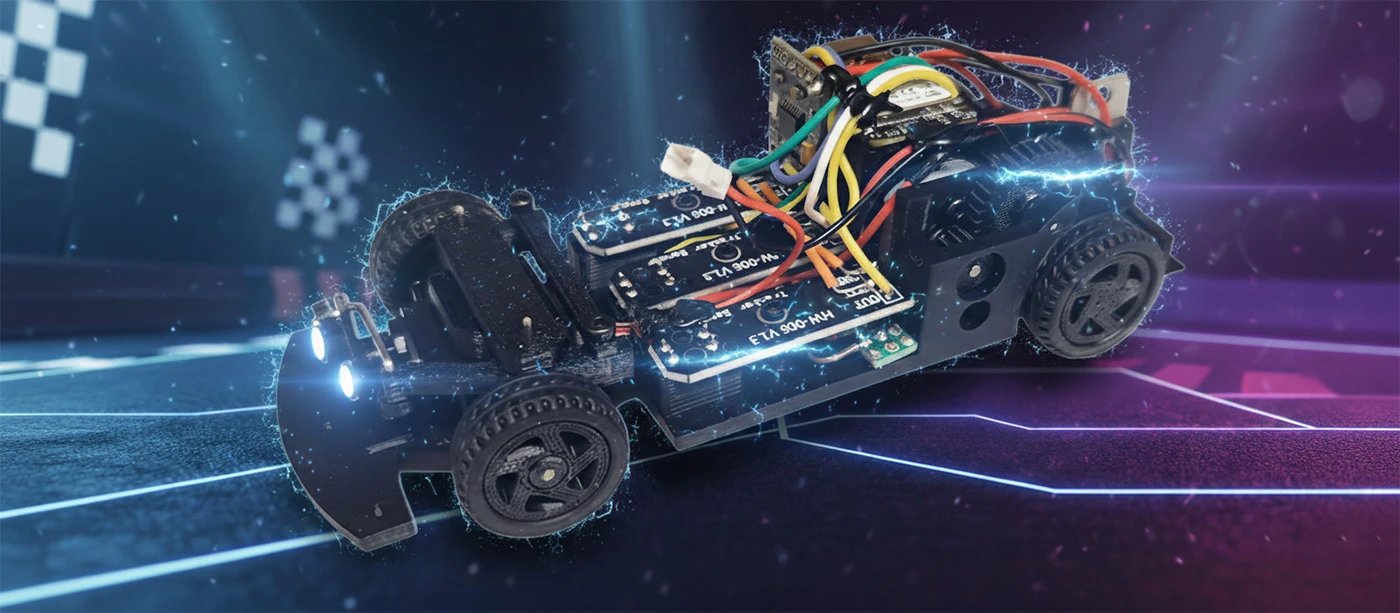
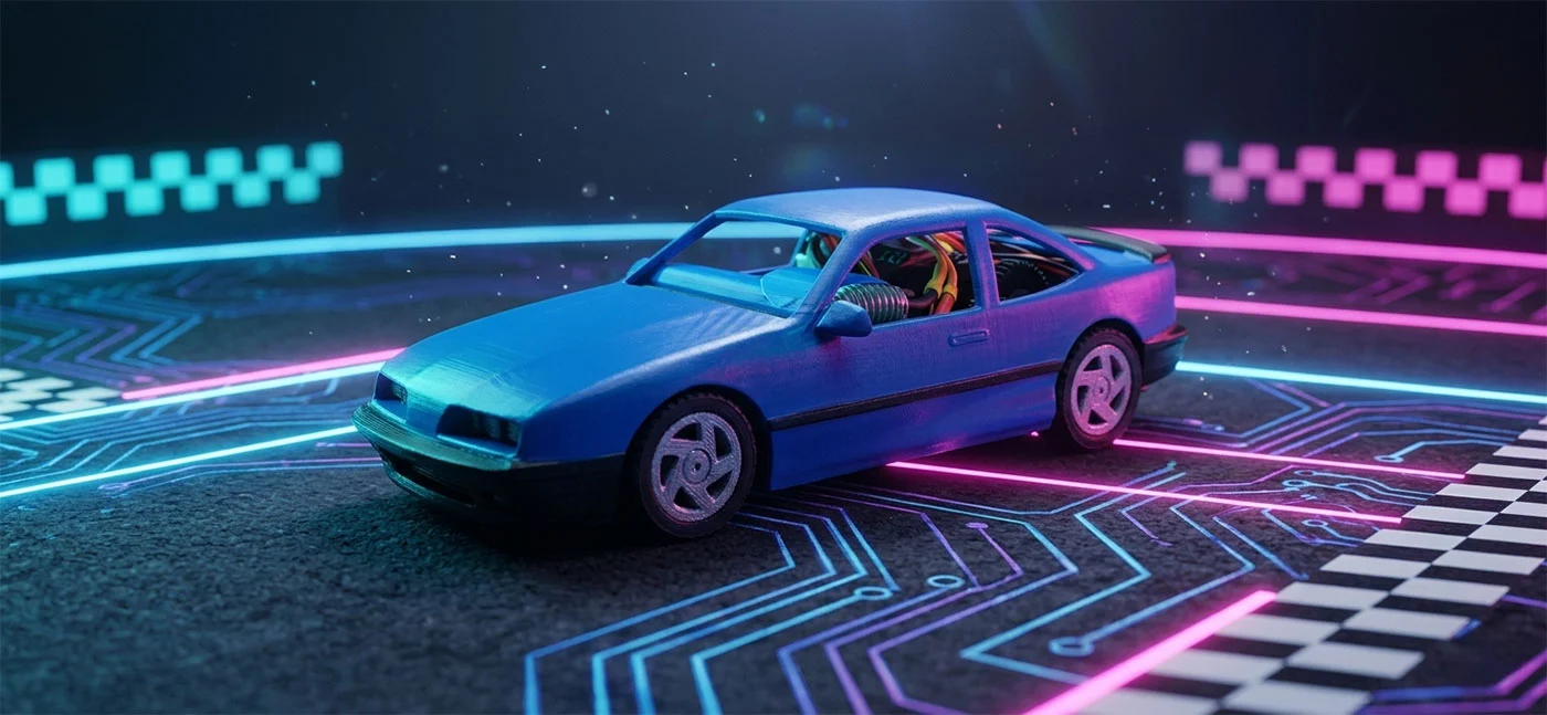
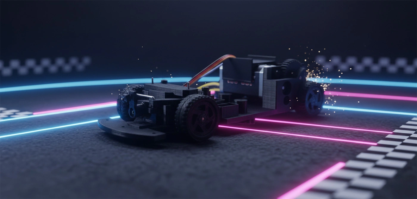
Let's shrink the engineering lab down to a 1:32 scale for a high-octane DIY build. In this project, I'll be 3d printing a custom chassis from the ground up and rigging it with a Bluetooth-enabled control stack
for precision handling via your favorite device.
Looking to ditch the driver? Let's bake in an optional Autonomous Navigation Mode for those who want to experiment with self-driving logic—just keep in mind this "autopilot" upgrade requires
some extra hardware calibration and a bit more code under the hood.
Ready to dive into the schematics? Check out the deep-dive documentation and high-definition video breakdowns for the full technical post-mortem on this build.
>> 01: HARDWARE
Scan the Hardware Manifest for a complete tactical breakdown of the components powering this build. While these specific parts aren't "hard-coded" requirements for a functional result, they serve as the proven blueprint I used to achieve peak performance. Consider them your verified reference guide. Keep in mind: since this build relies on additive manufacturing, you'll need a 3D printer on standby to hit those exact design tolerances and specifications. Ready to initialize the build? Let’s spool up.
Pro-Tips for the Build
- Interchangeability: If you have favorite servos or chips, feel free to swap them in—just watch your mounting points!
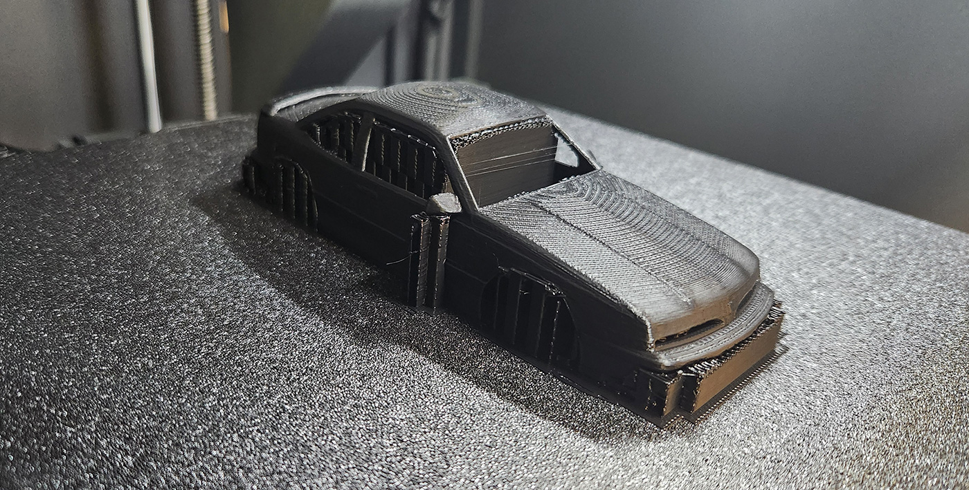
- Print Quality: For a 1:32 scale, I recommend printing layer size to be 0.12mm and I use PLA+ but many filaments will work.
>> 02: 3D PRINTED PARTS
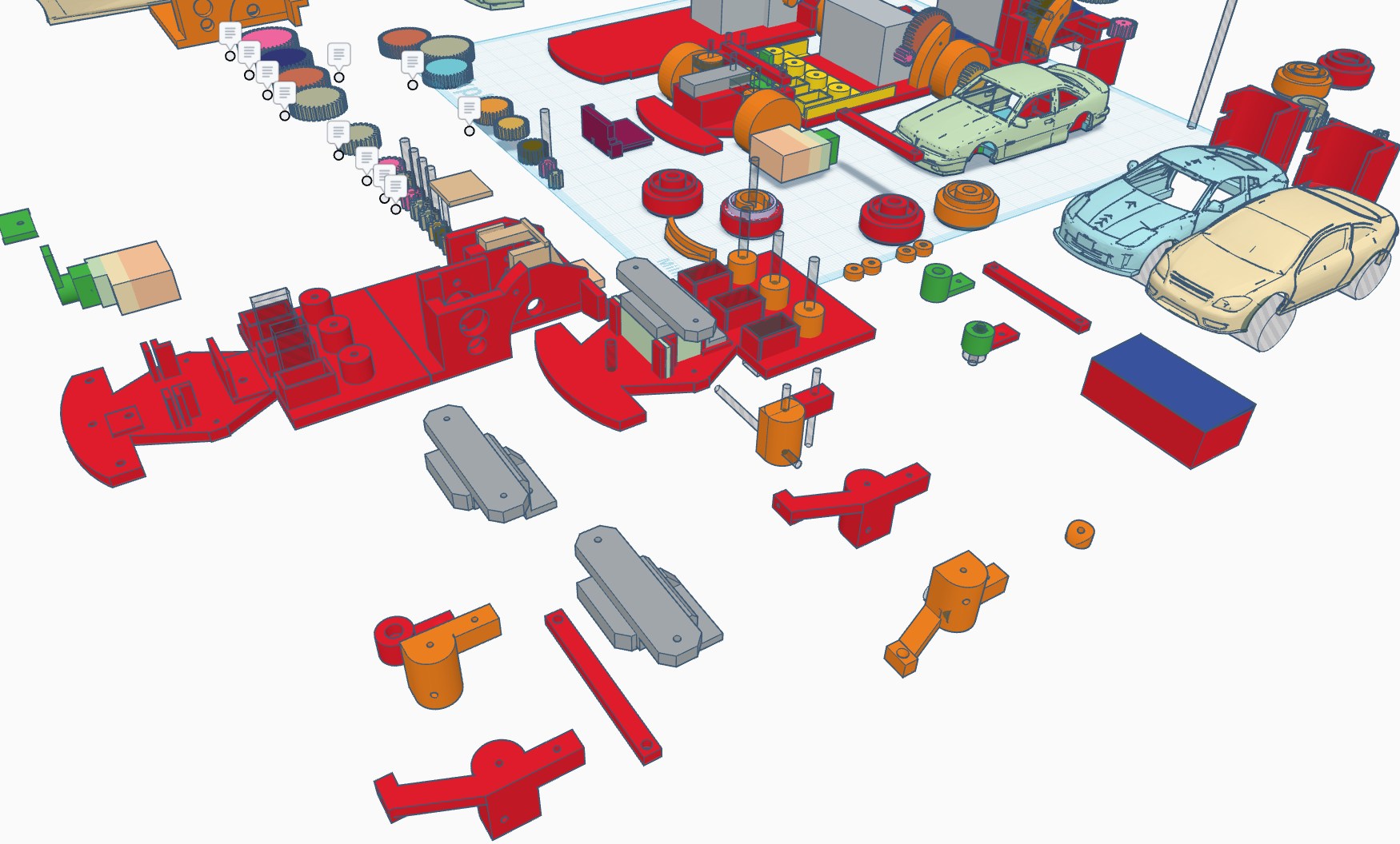
Initiate the data transfer! Head over to the Development Guide section to pull the source files for all 3D-printable geometries. Utilizing these pre-vetted STLs will streamline your assembly
workflow and ensure your tolerances stay razor-sharp.
Once you've got the functional foundation down, the floor is yours for some creative "over-engineering." Feel free to iterate on the chassis or push the envelope with aesthetic mods—give it some
aerodynamic flair or a custom shell that screams high-performance.
Assembly Directives
- File Origin: Locate the download links in the Development Guide.
- Workflow: Printing the verified files first ensures a "plug-and-play" experience.
- Creative License: I provide the skeletons; you provide the soul. Custom skins and spoilers are highly encouraged.
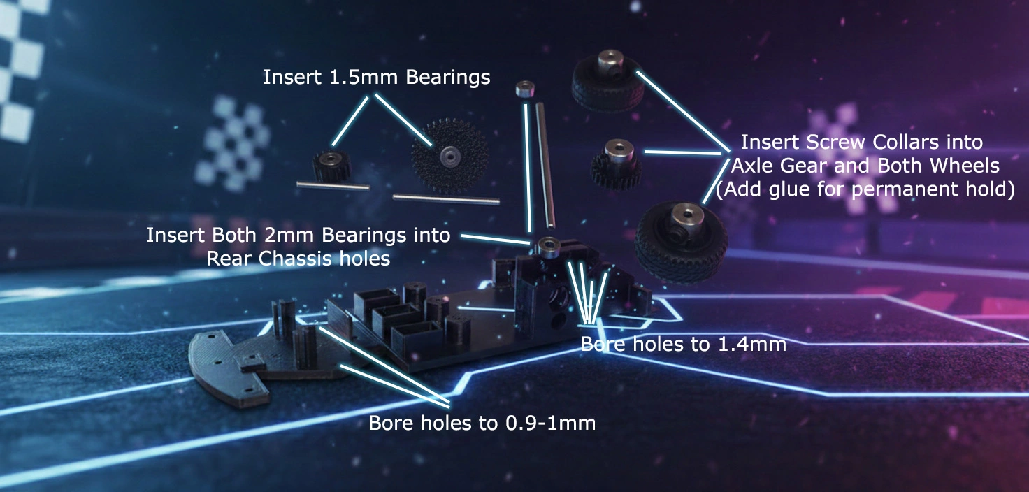
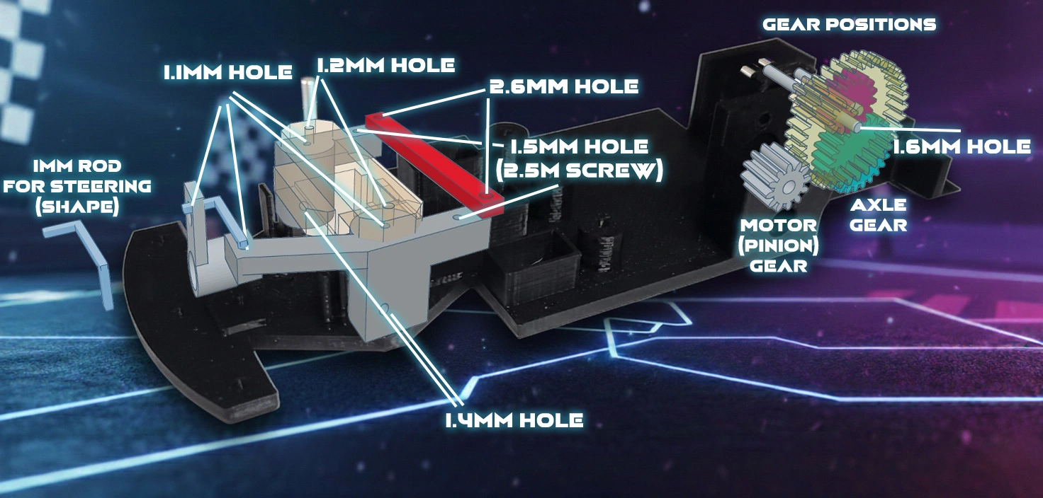
>> 03-04: CHASSIS PREP ASSEMBLY
It's time to transition from digital blueprints to physical assembly. Phase one: Chassis Integration.
Once your printer has finished extruding the core components, consult the Chassis Assembly Prep doc and initialize your "cold-start."
See the Chassis Prep video guide and ensure every mounting point is cleared and ready for hardware. For the full play-by-play, fire up the "Chassis Assembly" video tutorial below -
we're going deep into the mechanical guts.
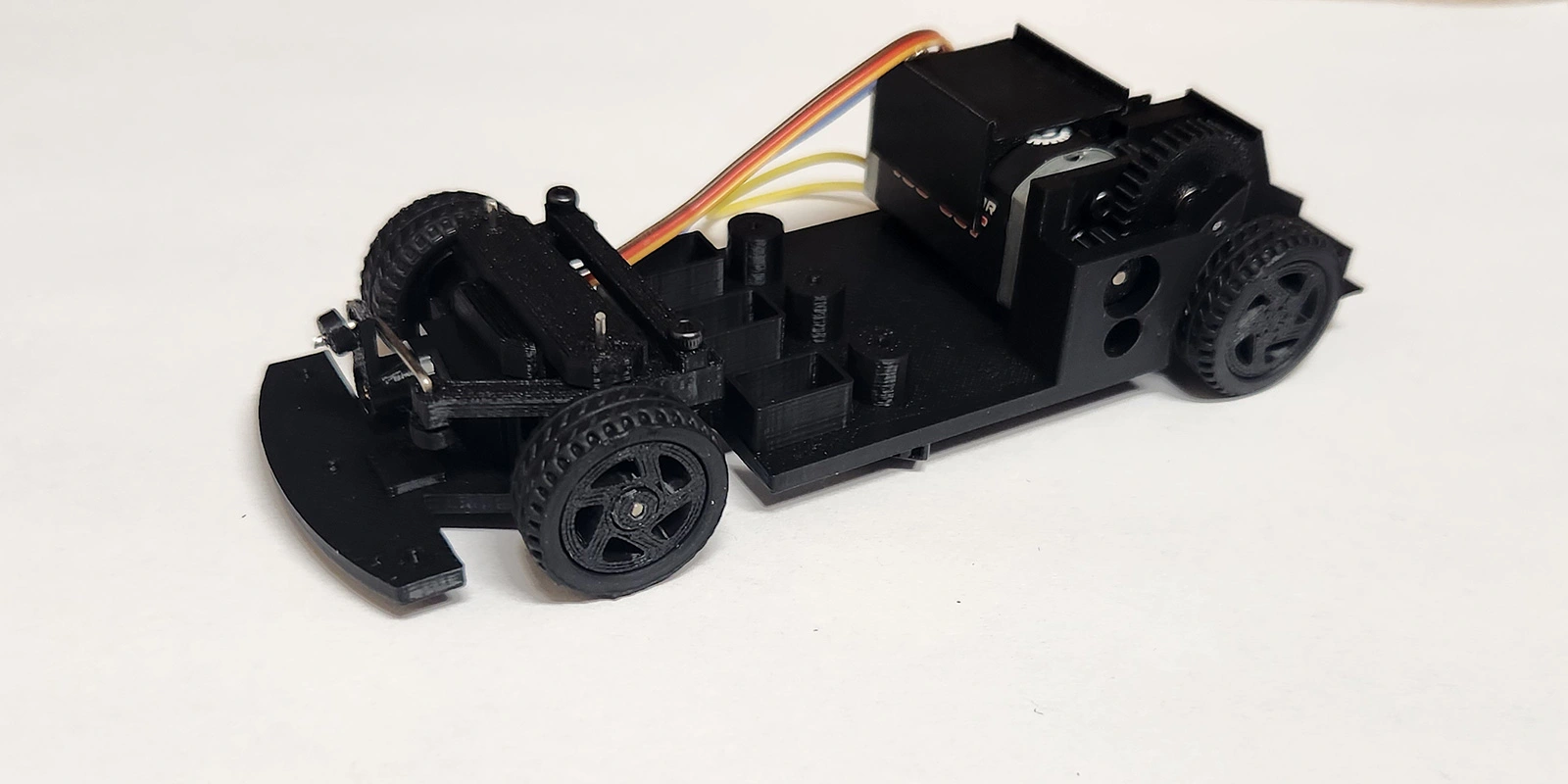
We'll be calibrating the gear mesh, locking in the wheel assemblies, and centering the steering rack. By the time the final screw is torqued, we'll have a rolling chassis primed for its electronic nervous system! Watch the
Chassis Assembly video guide for a detailed walkthrough.
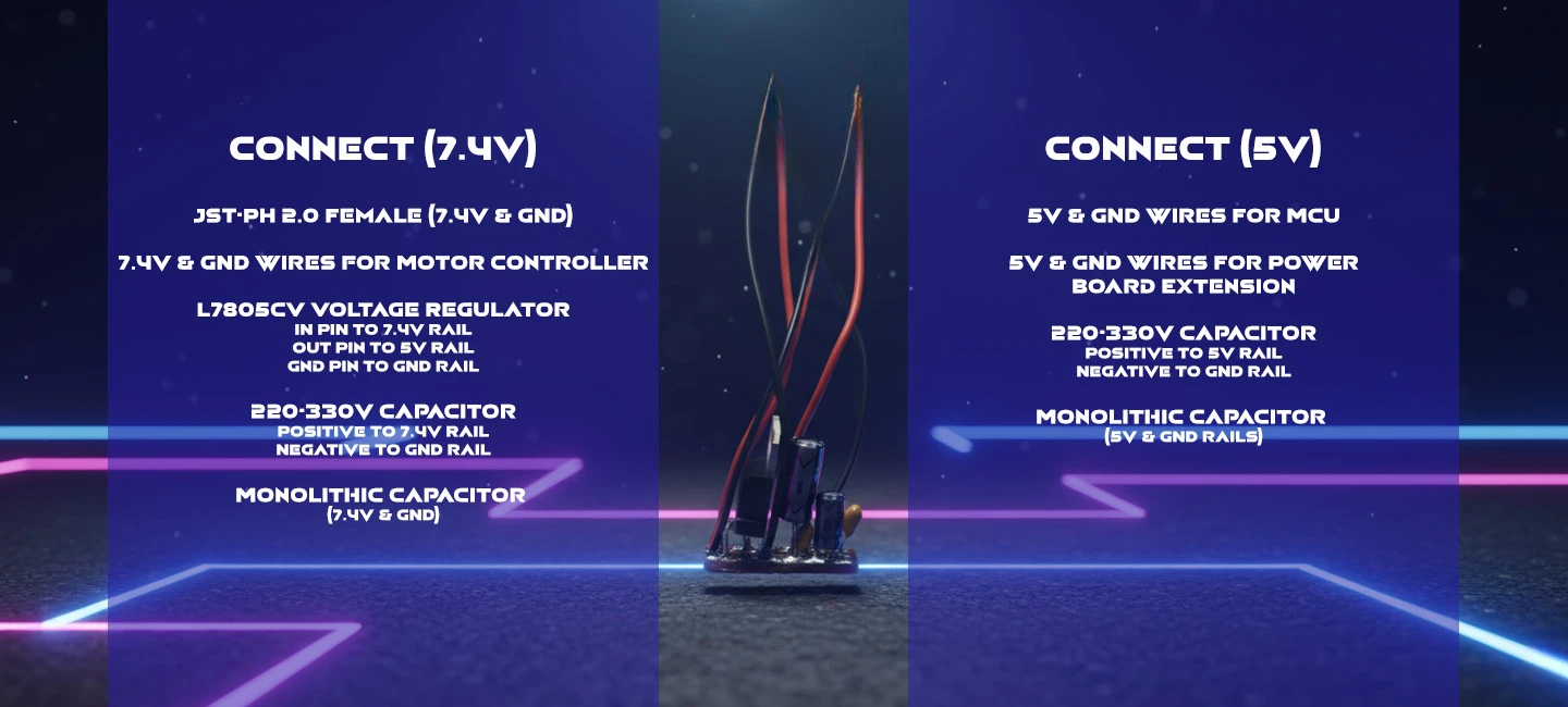
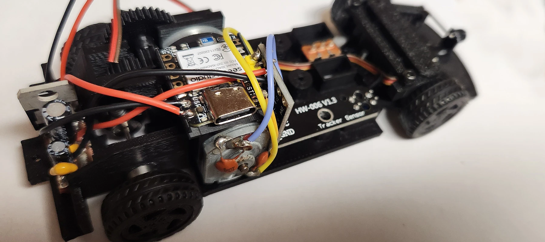
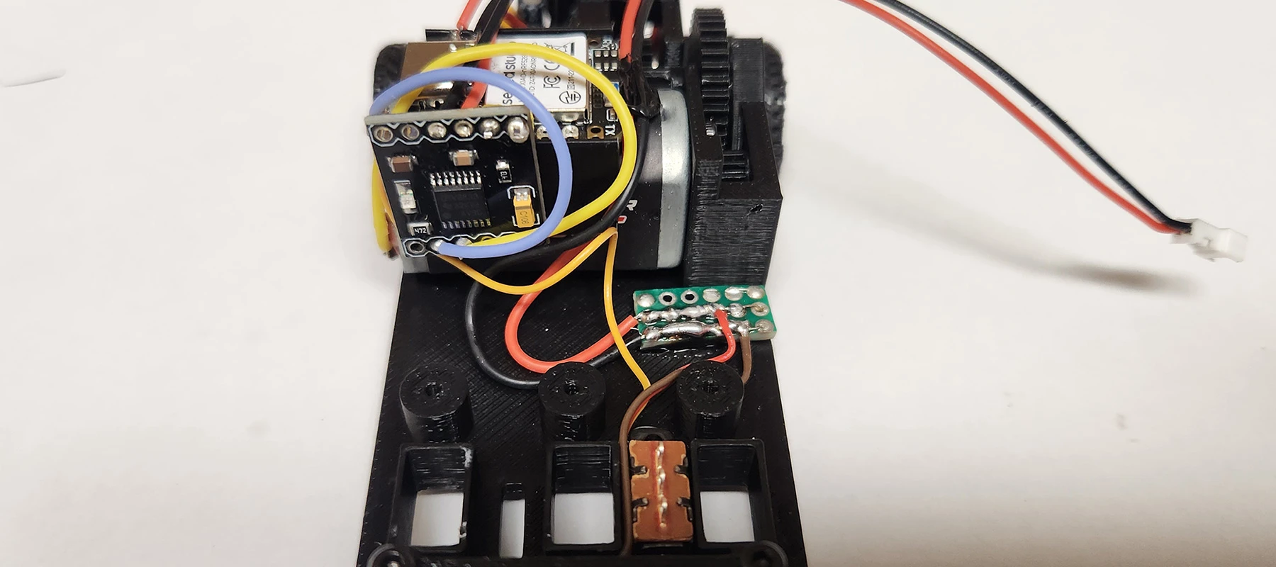
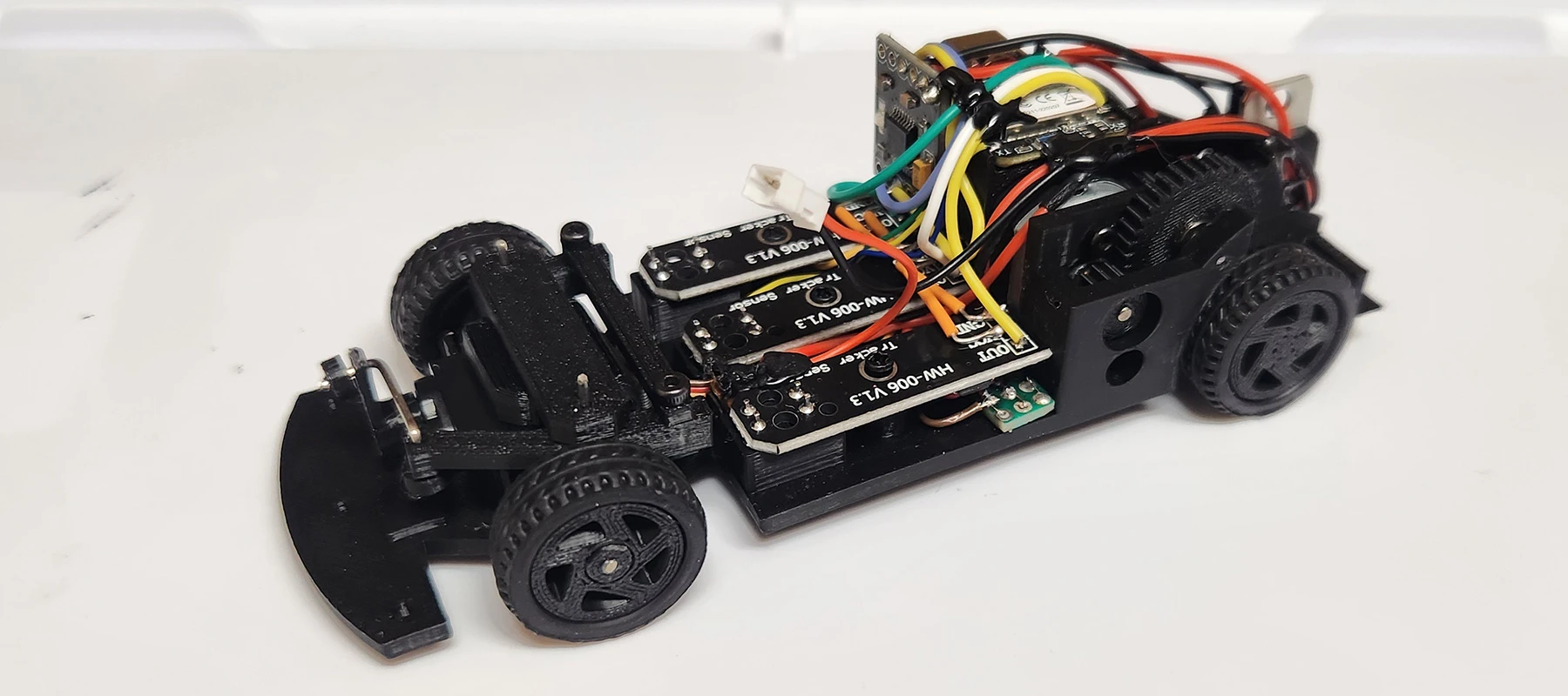
>> 05: ELECTRONIC COMPONENTS
Let's bring our 1:32 scale rig to life by installing the "nervous system." In this session, we're moving beyond the mechanical and diving into the silicon, where we'll be mounting and soldering the core electronic payload.
Get your soldering irons up to temp—we're establishing the high-speed data links and power rails required for smartphone-to-chassis communication. And don't forget, we're still on track to deploy the Autonomous Navigation
Module later in the series, so keep those solder joints clean for the upcoming sensor upgrades!
Check out the Electronic Components assembly video guide and/or view
the Circuit Diamgram documentation.
Mission Objectives
- Component Seating: Securing the MCU and motor drivers within the chassis housing.
- Thermal Bonding: Precision soldering of the power and signal leads.
>> 06: PROGRAM MANUAL DRIVE
Now we're ready for software development and deployment. The hardware is locked and the circuits are hot—now it's time to inject the "logic" that brings this 1:32 scale beast to life.
In this session, we're firing up the Arduino IDE to compile and flash the master control code. We'll be translating your smartphone’s touch inputs into real-time motor commands and steering vectors, ensuring
the microcontroller orchestrates every bit of data with millisecond precision.
Check out the Car Control Programming video guide and download the Arduino sketch found in the Project Build - Development Guide section of this tutorial.
Mission Objectives
- Environment Setup: Configuring the Arduino IDE for our specific chipset. The XIAO MCUs in this guide require Seeed Studio board package(s) added to the Arduino IDE, which can be found on their wiki page.
- Logic Implementation: Writing the code for Bluetooh connection, steering and PWM motor control.
- Download the Arduino Sketch for the full source code.
Code Breakdown
Libraries & Variables Overview
// Include necessary libraries and define variables
#include <ArduinoBLE.h>
#include <Servo.h>
#include <Wire.h>
#include "Adafruit_TCS34725.h"

#define MOT_A1_PIN A2
#define MOT_A2_PIN A3
#define SENSOR_L D8
#define SENSOR_M D9
#define SENSOR_R D10

// Setup Bluetooth Low Energy Service
BLEService comService("19B10000-E8F2-537E-4F6C-D104768A1214");
BLEStringCharacteristic controlCharacteristic("19B10000-E8F2-537E-4F6C-D104768A1215", BLERead | BLEWrite, 20);

// Initialize steering variables
// How far left the wheels can turn
const int STEER_CAR_MIN = 900;

// How far right the wheels can turn
const int STEER_CAR_MAX = 2100;

// Center steering
const int STEER_CAR_MID = 1500;

// Initialize all other variables
Code Breakdown
Setup Overview
// Setup Function
void setup() {
	// Begin BLE initialization
	if (!BLE.begin()) {
	while (1);
}

// set advertised local name and service UUID:
BLE.setLocalName("YOUR_CAR_NAME_HERE");
BLE.setAdvertisedService(comService);

// add the characteristic to the service
comService.addCharacteristic(controlCharacteristic);

// add service
BLE.addService(comService);

// set the initial value for the characeristic:
controlCharacteristic.writeValue("0");

// start advertising
BLE.advertise();

//Set Pin OUT on Motor Pins
pinMode(MOT_A1_PIN, OUTPUT);
pinMode(MOT_A2_PIN, OUTPUT);

//Setup and Center Steering
steer = STEER_CAR_MID;
steerServ.attach(D0);
Code Breakdown
Loop Overview
// Loop Function
void loop() {

// listen for Bluetooth peripherals to connect:
BLEDevice central = BLE.central();

// if a central is connected to peripheral:
if (central) {

// while the central is still connected to peripheral:
while (central.connected()) {

// if information is received.
if (controlCharacteristic.written()) {

// Get Values from BT app and assign to string
bleString = controlCharacteristic.value();
// Split and assign String to independant variables.
bleSpeed = getValue(bleString,',',0).toInt();

/* control the vehicle based on values */

// If mode is set to manual drive
if (bleMode == "M") {

// If speed is a positive number, go forward
if (bleSpeed > 0) {
	analogWrite(MOT_A1_PIN, 0);
	analogWrite(MOT_A2_PIN, speed);
}
else if (bleSpeed < 0) {
	// if negative number, go in reverse
	analogWrite(MOT_A1_PIN, 35);
	analogWrite(MOT_A2_PIN, 0);
} else {
	// if 0, stop the car
	analogWrite(MOT_A1_PIN, 0);
	analogWrite(MOT_A2_PIN, 0);
}

// Map steering and send value to servo
steer = map(bleSteer, STEER_SERVO_MIN, STEER_SERVO_MAX, STEER_CAR_MIN, STEER_CAR_MAX);
steerServ.writeMicroseconds(steer);
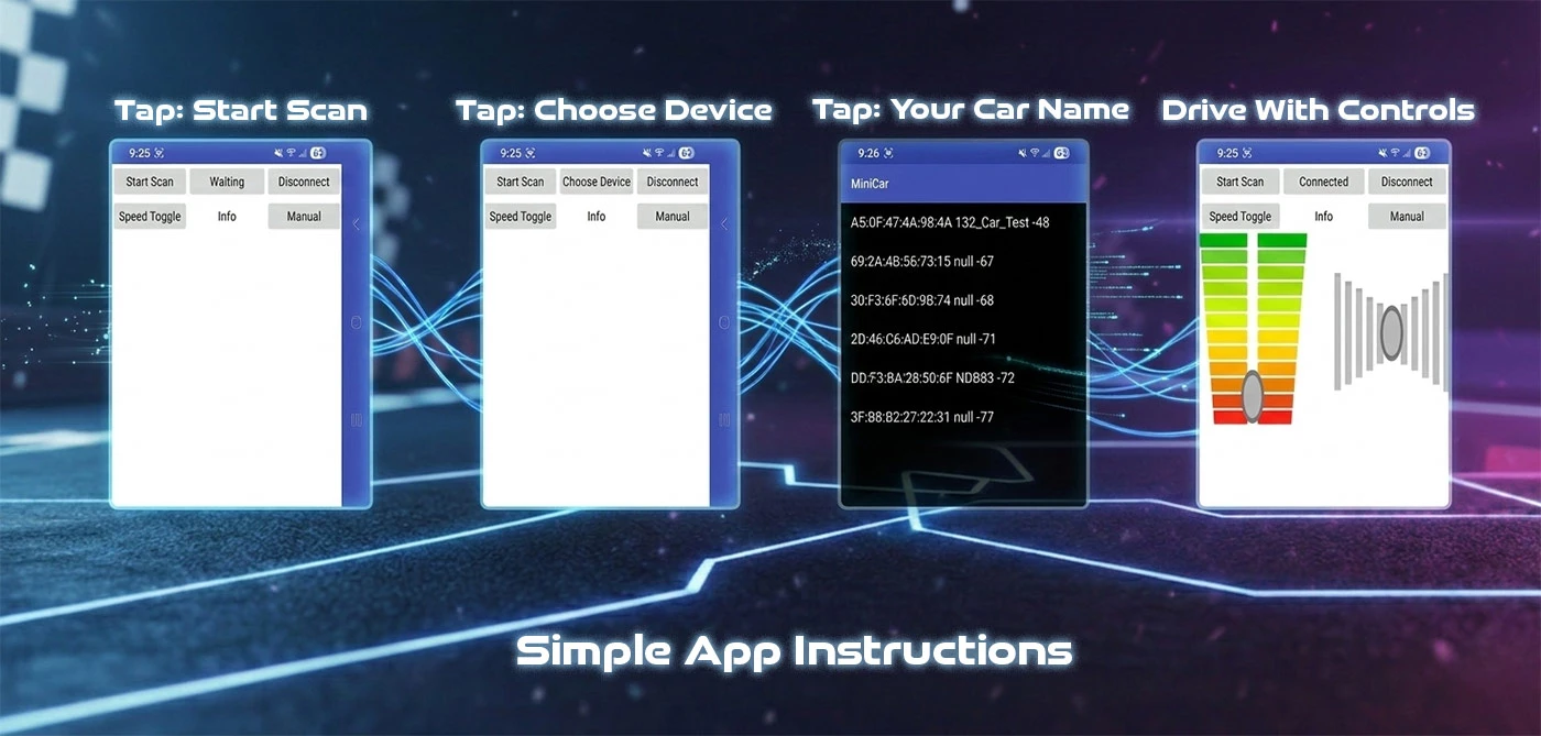
>> 07: CONTROLLER APP
Shifting gears, let's set our focus on the high-level control layer as we architect a custom interface using the MIT App Inventor framework.
In this module, we're leveraging block-based logic to expedite the development of our mobile command center. This approach allows us to bypass low-level mobile coding and jump straight into deploying a functional Manual
Control Stack—giving you tactile, real-time command over your 1:32 scale interceptor with a custom-built digital cockpit. View the Controller App Video Guide.
Project Goals
- Download and install the MIT App Inventor App for Bluetooth connectivity.
- Alternatively, download the MIT App Inventor Project and load it up on your own to tweak the controller.
- Download All Project Files
>> 08: SELF DRIVING
We've mastered manual remote piloting—now it's time to upgrade the "brain." In this session, we're returning to the MIT App Inventor environment to overhaul our control interface and deploy the highly anticipated Auto-Drive Mode.
But we're not just coding in a vacuum. We'll also be engineering a DIY specialized track from scratch. This custom testing ground will serve as the "proving lab" where we'll calibrate the car's sensors and logic to
navigate complex lines and hairpins with zero human intervention.
Technical Objectives
- Track Fabrication: Constructing a high-contrast DIY circuit optimized for our micro-chassis.
- Logic Calibration: Adding additional variables and control logic to the Adruino code.
- UI Refactoring: Updating the MIT App Inventor stack with autonomous toggle switches.
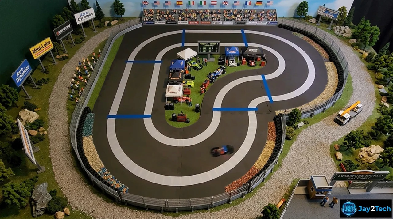
>> 08A: TRACK BUILD
After successfully clearing the mechanical assembly and establishing a rock-solid manual control link - now, it's time to pivot toward Autonomous Navigation.
Before we can initialize the self-driving logic, we need to construct the physical environment our sensors will interface with. This module focuses entirely on Track Fabrication. We'll be engineering a high-contrast
DIY circuit designed specifically for our 1:32 scale rig's sensor array to scan, interpret, and conquer. Check Out the Track Build video or keep following along here.
Tactical Objectives
- Infrastructure Build: Constructing a custom-scale track optimized for optical or infrared feedback.
- Surface Calibration: Ensuring the track material provides the necessary "readability" for our micro-chassis.
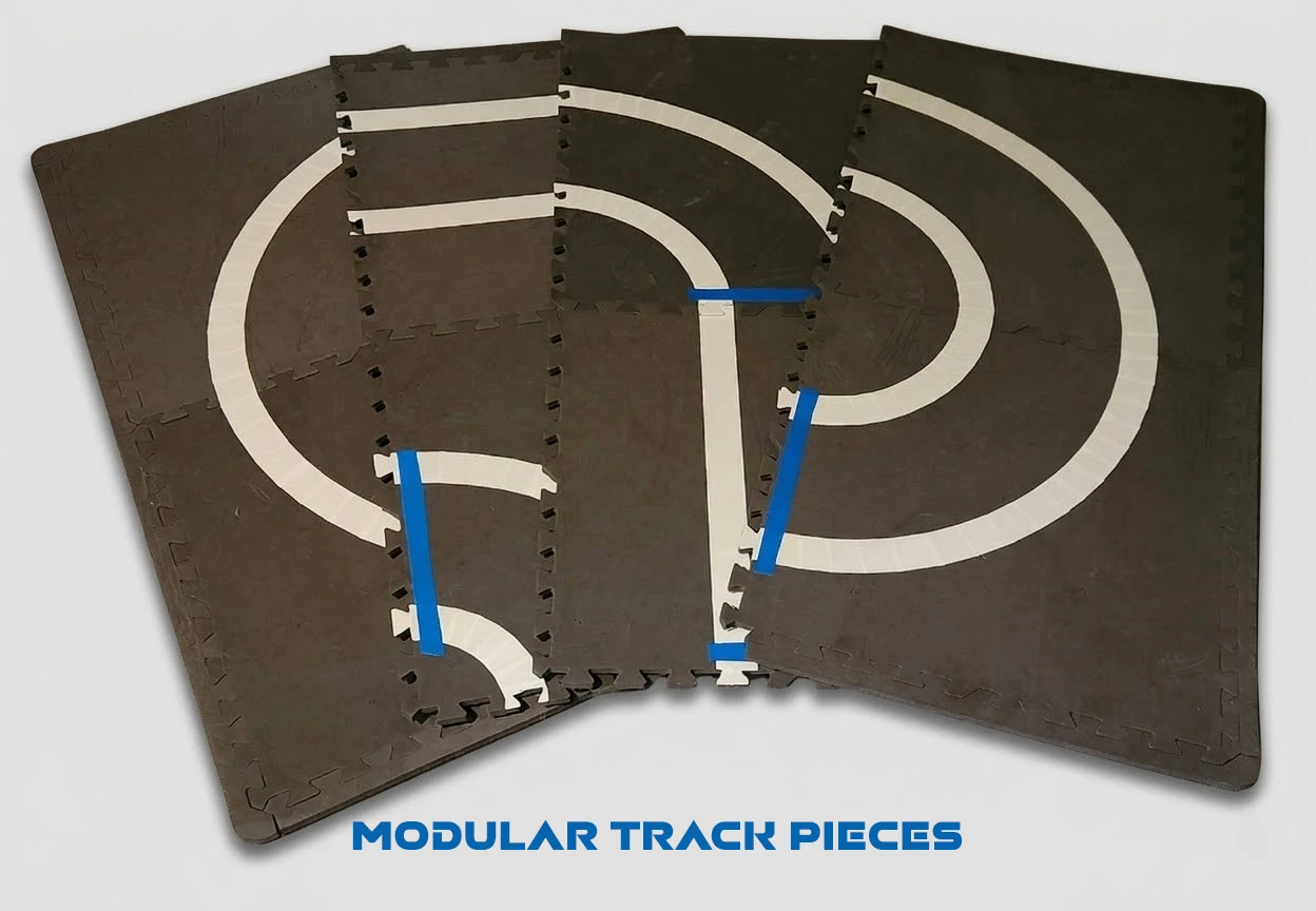
- Pro Tip: Make the track pieces modular, which makes it possible to mix and match track pieces.
- Check out the Track Manifest to see a list of products I used for making the track.
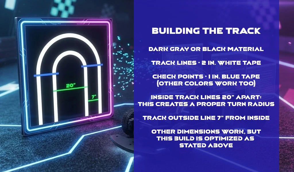
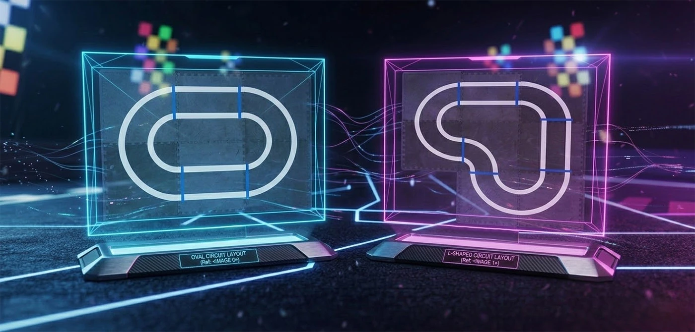
Track Design Notes
- Blue tape used as checkpoints: should be 1 - 2 inches after the track piece starts, not before (see above image).
- Blue color tape not required. However, the arduino sketch is calibrated for blue.
- Diameter of each turn should be roughly 20 inches for best result (see image above).
- Outside track line 7 inches from inside track line (see image above).
- Following this layout provides the option for both Self-Driving methods, (line follower or line avoider).
>> 08B: PROGRAM SELF DRIVE
We've successfully engineered the physical proving grounds—now it's time to upload the "instincts."
We're returning to the Arduino IDE to refactor our firmware for closed-loop navigation. We'll be deploying the sensor-processing logic that allows our 1:32 scale rig to interpret track data in real-time,
transitioning from a remote-piloted vehicle to a fully reactive, self-correcting autonomous machine.
Code Objectives
- Logic Integration: Writing the conditional "if-then" branching or PID loops required for line-following precision.
- I/O Initialization: Configuring the high-speed pins for our infrared/optical sensor array.
- Download The Arduino Sketch for the full code.
Code Breakdown
Self-Driving Variable Updates
// Define Color Sensor
Adafruit_TCS34725 tcs = Adafruit_TCS34725(TCS34725_INTEGRATIONTIME_2_4MS, TCS34725_GAIN_60X);

// New Characteristic to read information (Lap counter, Lap time, etc.)
BLEStringCharacteristic reportCharacteristic("19B10000-E8F2-537E-4F6C-D104768A1216", BLERead | BLEWrite | BLENotify, 20);

// Define Infrared Sensors)
#define SENSOR_L D8
#define SENSOR_M D9
#define SENSOR_R D10

// Several new varaibles
String TRACK_POS = "mid";
String COLOR_CODE = "";
String trackDirection = "S";

// HERE IS HOW WE DEFINE TRACK CHECKPOINTS
// L = left turn, S = Straight, R = Right Turn
// My Example Track 1
String track1Array[] = {"L", "S", "L", "S"};

// My Example Track 2
String track2Array[] = {"L", "R", "L", "S", "L","S"};
int trackLength = sizeof(track2Array) / sizeof(track2Array[0]);

// When array is complete and checkpoint returns to first element in array
// Lap Counter increments by 1
int lapCounter = 0;
int trackStage = -1;

// Other variables.
Code Breakdown
Self-Driving Setup Updates
// Add New Characteristic
comService.addCharacteristic(reportCharacteristic);

// Write initial value for new characteristic
reportCharacteristic.writeValue("0");

// Begin Color Sensor
if (!tcs.begin()) {
	while (1);
}

// Set sensors as input
pinMode(SENSOR_L, INPUT);
pinMode(SENSOR_M, INPUT);
pinMode(SENSOR_R, INPUT);

// Turn off sensor LED to start
tcs.setInterrupt(true);
Code Breakdown
Self-Driving Loop Updates
// IF driving mode set to Auto
else if (bleMode == "A") {

// IF self driving turned on and lapCounter < Total Laps to drive
if (bleAuto == 1 lapCounter < autoDriveLaps) {

// A lot of driving Logic with some important things to Note

// Turn on color sensor LED
tcs.setInterrupt(true);

// Read track for color Changes
tcs.getRGB(&red, &green, &blue);

// Read track IR senors
SENSOR_L_VAL = digitalRead(SENSOR_L);
SENSOR_M_VAL = digitalRead(SENSOR_M);
SENSOR_R_VAL = digitalRead(SENSOR_R);

// Lap Counter increment
lapCounter ++;

// This sends data back to phone to report current lap
String dataToSend = String(lapCounter);
reportCharacteristic.writeValue(dataToSend);

// When auto drive turns off, reset variables.
>> 08C: CONTROLLER APP SELF DRIVE
Command Protocol Expansion. We've tuned the chassis and mapped the track—now we're finalizing the "Over-the-Air" instructions to trigger autonomous driving. Watch the
Self Driving video guide for a complete visual walkthrough.
In this continuation, we're refactoring our MIT App Inventor logic to include the Auto-Drive Toggle. We'll be focusing on the specific data packets and command strings transmitted from your device to the car's microcontroller.
This update allows you to flip a digital switch on your screen and instantly hand over the steering wheel to the car's onboard logic.
Interface Objectives
- Control Layer Refactoring: Integrating the "Autonomous Mode" UI button and state indicators.
- Protocol Transmission: Mapping the specific Bluetooth character codes that tell the Arduino to switch from Manual to Auto.
- Latency Calibration: Ensuring the car receives and executes the "Self-Drive" command with zero delay.
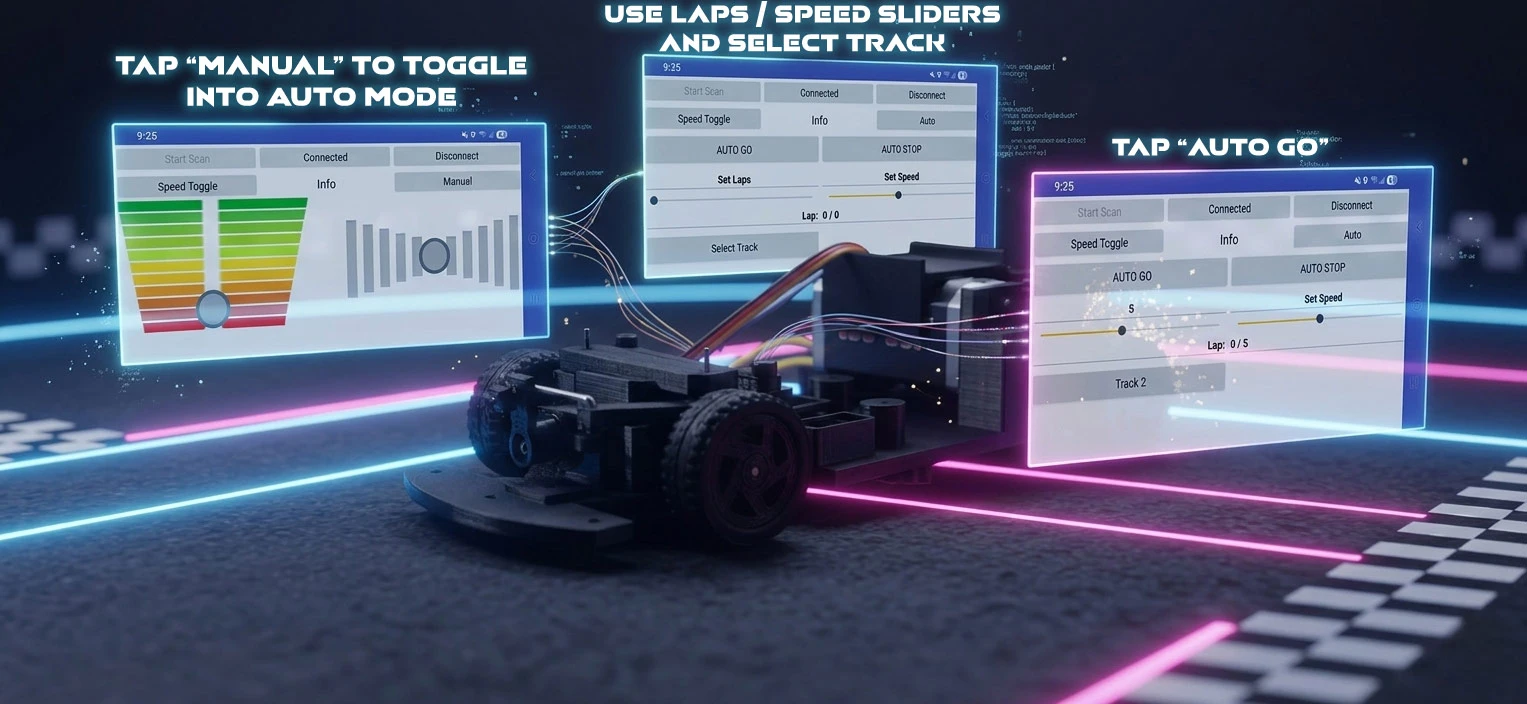
Audo Drive Notes
- The cars starting area must be between the first checkpoint and last checkpoint.
- Pro Tip: Currently the ideal speed is between 32-38 on the speed slider.
- View the Self Driving Update video guide.
>> CAR_COMPONENT_MANIFEST
* Product links will not be updated in the future *
| REF_ID | DESCRIPTION | APPROXIMATE COST | SOURCING |
|---|---|---|---|
| MCU | Xiao nRF52840 | $9.99 - $18.99 | AMAZON / SeeedStudio |
| MOTOR | 7.2V 180 RC Bushed Motor | $9.99 - $15.99 | AMAZON |
| MOTOR CONTROLLER | DRV8833 Motor Drive Module | $1.50 - $3.00 each | AMAZON |
| BATTERY | 7.4V LiPo Battery 400mAh | $12.00 each | AMAZON |
| STEERING | 2.1g Servo DM-S0020 | $4.00 - $5.00 each | AMAZON |
| REGULATOR | 5V 1.5A Regulator | $0.25 - $0.35 each | AMAZON |
| ELECTRICAL | Solderable Breadboard | Many Options | AMAZON |
| MOUNTING | M2 Screws | $7.99 | AMAZON |
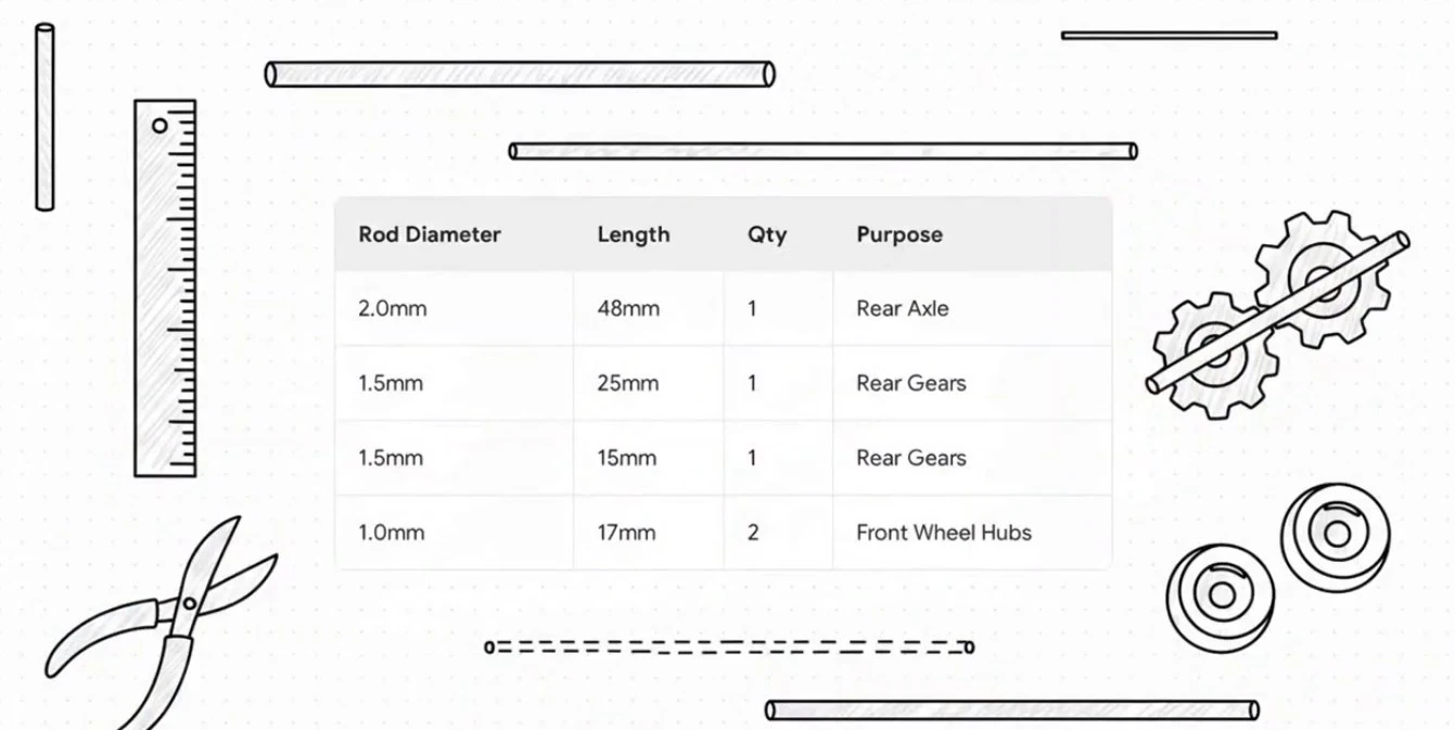
| HARDWARE | 1mm, 1.5mm & 2mm Rods | $9.99 | AMAZON |
| HARDWARE | 1.5mm Flanged Bearings | $12.79 (set of 20) | AMAZON |
| HARDWARE | 2mm Bearings | $9.99 (set of 20) | AMAZON |
| HARDWARE | 2mm Lock Collars | $6.49(set of 10) | AMAZON |
| HARDWARE | 20mm Rubber Tires | $10.20 - $17.76(set of 50) | EBAY / AMAZON |
>> CAR_COMPONENT_MANIFEST
| REF_ID | DESCRIPTION | APPROXIMATE COST | SOURCING |
|---|---|---|---|
| HARDWARWE | 3 Pin Toggle Switch | $5.99 - $7.99 (set of 50) | AMAZON |
| SENSOR | TCS34725 Color Sensor | $4.00 each | AMAZON |
| SENSOR | HiLetgo TCRT5000 (x3) | $7.89 (set of 5) | AMAZON |
| CAPACITOR | Electrolytic Capacitor (x2) | $7.99 (set) | AMAZON |
| CAPACITOR | 100nF Monolithic Capacitor (x2) | $6.99 (set of 120) | AMAZON |
| BATTERY CONNECTOR | JST-PH 2.0 | $7.69 (10 pairs) | AMAZON |
>> TRACK_COMPONENT_MANIFEST
| REF_ID | DESCRIPTION | APPROXIMATE COST | SOURCING |
|---|---|---|---|
| TRACK BASE | Gym Flooring Tiles | $21.97 (case 24 sq. ft.) | HOME DEPOT |
| TAPE | 3M Multi-Use White Tape | $5.28 - $5.78 | AMAZON / HOME DEPOT |
| TAPE | Multi-Color Tape Set | $20.58 | AMAZON |